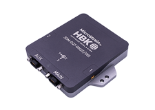
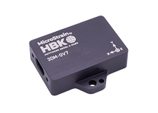
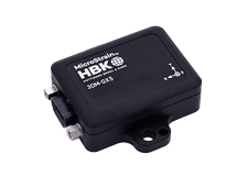
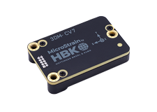
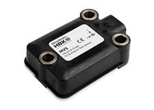
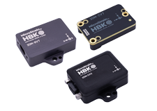
The 3DM-GX4 -25™ is a miniature industrial-grade attitude heading and reference system (AHRS) with integrated magnetometers, high noise immunity, and exceptional performance.
Product Highlights
- High performance integrated MEMS sensor technologyprovide direct and computed AHRS outputs in a small package.
- Triaxial accelerometer, gyroscope, magnetometer, temperature sensors, and a pressure altimeter achieve the best combination of measurement qualities.
- Dual on-board processors run a sophisticated AdaptiveKalman Filter (AKF) for excellent static and dynamic attitude estimates and inertial measurements.
The 3DM-GX4-15™ is a miniature industrial-grade inertial measurement unit (IMU) and vertical reference unit (VRU) with high noise immunity, and exceptional performance.
Product Highlights
- High performance integrated MEMS sensor technology provide direct and computed IMU and VRU outputs in a small package.
- Triaxial accelerometer, gyroscope, temperature sensors, and a pressure altimeter achieve the best combination of measurement qualities.
- Dual on-board processors run a sophisticated Adaptive Kalman Filter (AKF) for excellent static and dynamic inclination estimates and inertial measurements.
The 3DM-GX4-45™ is a miniature industrial-grade all-in-one navigation solution with integrated GPS and magnetometers, high noise immunity, and exceptional performance.
Product Highlights
- High performance integrated GPS receiver and MEMS sensor technology provide direct and computed PVA outputs in a small package.
- Triaxial accelerometer, gyroscope, magnetometer, temperature sensors, and a pressure altimeter achieve the best combination of measurement qualities.
- Dual on-board processors run a sophisticated Extended Kalman Filter (EKF) for excellent position, velocity, and attitude estimates.
Pages
Best in Class Performance
- Fully calibrated, temperature compensated, and mathematically aligned to an orthogonal coordinate system for highly accurate outputs
- Bias tracking, error estimation, threshold flags, and adaptive noise, magnetic, and gravitational field modeling allow for fine tuning to conditions in each application.
- High performance, low drift gyros with noise density of 0.005°/sec/√Hz and VRE of 0.001°/s/g2RMS
- Smallest and lightest industrial AHRS available
Ease of Use
- User-defined sensor-to-vehicle frame transformation
- Easy integration via comprehensive SDK
- Common protocol with the 3DM-GX3® and 3DM-RQ1-45™ sensor families for easy migration
Cost Effective
- Out-of-the box solution reduces development time.
- Volume discounts
Best in Class Performance
- Fully calibrated, temperature compensated, and mathematically aligned to an orthogonal coordinate system for highly accurate outputs
- Bias tracking, error estimation, threshold flags, and adaptive noise, magnetic, and gravitational field modeling allow for fine tuning to conditions in each application.
- High performance, low drift gyros with noise density of 0.005°/sec/√Hz and VRE of 0.001°/s/g2RMS
- Smallest and lightest industrial AHRS available
Ease of Use
- User-defined sensor-to-vehicle frame transformation
- Easy integration via comprehensive SDK
- Common protocol with the 3DM-GX3® and 3DM-RQ1- 45™ sensor families for easy migration
Cost Effective
- Out-of-the box solution reduces development time.
- Volume discounts
Best in Class Performance
- Fully calibrated, temperature compensated, and mathematically aligned to an orthogonal coordinate system for highly accurate outputs
- Bias tracking, error estimation, threshold flags, and adaptive noise, magnetic, and gravitational field modeling allow for fine tuning to conditions in each application.
- High performance, low drift gyros with noise density of 0.005°/sec/√Hz and VRE of 0.001°/s/g2RMS
- Smallest and lightest industrial GPS/INS available
Ease of Use
- User-defined sensor-to-vehicle frame transformation
- Easy integration via comprehensive SDK
- Common protocol with the 3DM-GX3® and 3DM-RQ1-45™ sensor families for easy migration
Cost Effective
- Out-of-the box solution reduces development time.
- Volume discounts
Pages
|
General |
|||
|---|---|---|---|
|
Integrated sensors |
Triaxial accelerometer, triaxial gyroscope, triaxial magnetometer, temperature sensors, and pressure altimeter |
||
|
Data outputs |
Inertial Measurement Unit (IMU) outputs: acceleration, angular rate, magnetic field , ambient pressure, deltaTheta, deltaVelocity Computed outputs Adaptive Kalman Filter (AKF): filter status, GPS timestamp, attitude estimates (in Euler angles, quaternion, orientation matrix), bias compensated angular rate, pressure altitude, gravity-free linear acceleration, attitude uncertainties, gyroscope and accelerometer bias, scale factors and uncertainties, gravity and magnetic models, and more. Complementary Filter (CF): attitude estimates (in Euler angles, quaternion, orientation matrix), stabilized north and gravity vectors, GPS correlation timestamp |
||
|
Inertial Measurement Unit (IMU) Sensor Outputs |
|||
|
Accelerometer |
Gyroscope |
Magnetometer |
|
|
Measurement range |
±5 g (standard) ±16 g (option) |
300°/sec (standard) ±75, ±150, ±900°/sec (options) |
±2.5 Gauss |
|
Non-linearity |
±0.03 % fs |
±0.03 % fs |
±0.4 % fs |
|
Resolution |
<0.1 mg |
<0.008°/sec |
-- |
|
Bias instability |
±0.04 mg |
10°/hr |
-- |
|
Initial bias error |
±0.002 g |
±0.05°/sec |
±0.003 Gauss |
|
Scale factor stability |
±0.05 % |
±0.05 % |
±0.1 % |
|
Noise density |
100 µg/√Hz |
0.005°/sec/√Hz |
100 µGauss/√Hz |
|
Alignment error |
±0.05° |
±0.05° |
±0.05° |
|
Adjustable bandwidth |
225 Hz (max) |
250 Hz (max) |
- |
|
Offset error over temperature |
0.06% (typ) |
0.05% (typ) |
-- |
|
Gain error over temperature |
0.05% (typ) |
0.05% (typ) |
-- |
|
Scale factor non-linearity (@ 25° C) |
0.02% (typ) 0.06% (max) |
0.02% (typ) 0.06% (max) |
±0.0015 Gauss |
|
Vibration induced noise |
-- |
0.072°/s RMS/g RMS |
-- |
|
Vibration rectification error (VRE) |
-- |
0.001°/s/g2 RMS |
-- |
|
IMU filtering |
4 stage filtering: analog bandwidth filter to digital sigma- delta wide band anti-aliasing filter to (user adjustable) digital averaging filter sampled at 4 kHz and scaled into physical units; coning and sculling integrals computed at 1 kHz |
||
|
Sampling rate |
4 kHz |
4 kHz |
50 Hz |
|
IMU data output rate |
1 Hz to 1000 Hz |
||
|
Pressure Altimeter |
|||
|
Range |
-1800 m to 10,000 m |
||
|
Resolution |
< 0.1 m |
||
|
Noise density |
0.01 hPa RMS |
||
|
Sampling rate |
25 Hz |
||
|
Computed Outputs |
|||
|
Attitude accuracy |
AKF outputs: ±0.25° RMS roll & pitch, ±0.8° RMS heading (typ) CF outputs: ±0.5° roll, pitch, and heading (static, typ), ±2.0° roll, pitch, and heading (dynamic, typ) |
||
|
Attitude heading range |
360° about all axes |
||
|
Attitude resolution |
< 0.01° |
||
|
Attitude repeatability |
0.3° (typ) |
||
|
Calculation update rate |
500 Hz |
||
|
Computed data output rate |
AKF outputs: 1 Hz to 500 Hz CF outputs: 1 Hz to 1000 Hz |
||
|
Operating Parameters |
|||
|
Communication |
USB 2.0 (full speed) RS232 (9,600 bps to 921,600 bps, default 115,200) |
||
|
Power source |
+ 3.2 to + 36 V dc |
||
|
Power consumption |
100 mA (typ),120 mA (max) with Vpri = 3.2 V dc to 5.5 V dc 550 mW (typ), 800 mW (max) with Vaux = 5.2 V dc to 36 V dc |
||
|
Operating temperature |
-40 °C to +85 °C |
||
|
Mechanical shock limit |
500 g (calibration unaffected) 1000 g (bias may change) 5000 g (survivability) |
||
|
MTBF |
1.2 million hours (Telcordia method I, GL/35C) 0.45 million hours (Telcordia method I, GM/35C) |
||
|
Physical Specifications |
|||
|
Dimensions |
36.0 mm x 24.4 mm x 11.1 mm (excluding mounting tabs), 36.6 mm (width across tabs) |
||
|
Weight |
16.5 grams |
||
|
Enclosure material |
Aluminum |
||
|
Regulatory compliance |
ROHS, CE |
||
|
Integration |
|||
|
Connectors |
Data/power output: micro-DB9 |
||
|
Software |
MIP™ Monitor, MIP™ Hard and Soft Iron Calibration, Windows XP/Vista/7/8 compatible |
||
|
Compatibility |
Protocol compatibility with 3DM-GX3® and 3DM- RQ1-45™ sensor families. |
||
|
Software development kit (SDK) |
MIP™ data communications protocol with sample code available (OS and computing platform independent) |
||
|
General |
|||
|---|---|---|---|
|
Integrated sensors |
Triaxial accelerometer, triaxial gyroscope, temperature sensors, and pressure altimeter |
||
|
Data outputs |
Inertial Measurement Unit (IMU) outputs: acceleration, angular rate, ambient pressure, deltaTheta, deltaVelocity Computed outputs: Adaptive Kalman Filter (AKF): filter status, GPS timestamp, attitude estimates (Euler angles, quaternion, orientation matrix), bias compensated angular rate, pressure altitude, gravity-free linear acceleration, attitude uncertainties, gyroscope and accelerometer bias, scale factors and uncertainties, gravity models, and more. Complementary Filter (CF): attitude estimates (Euler angles, quaternion, orientation matrix), stabilized gravity vector, GPS correlation timestamp |
||
|
Inertial Measurement Unit (IMU) Sensor Outputs |
|||
|
Accelerometer |
Gyroscope
|
||
|
Measurement range |
±5 g (standard) ±16 g (option) |
300°/sec (standard) ±75, ±150, ±900°/sec (options) |
|
|
Non-linearity |
±0.03 % fs |
±0.03 % fs |
|
|
Resolution |
<0.1 mg |
<0.008°/sec |
|
|
Bias instability |
±0.04 mg |
10°/hr |
|
|
Initial bias error |
±0.002 g |
±0.05°/sec |
|
|
Scale factor stability |
±0.05 % |
±0.05 % |
|
|
Noise density |
100 µg/√Hz |
0.005°/sec/√Hz |
|
|
Alignment error |
±0.05° |
±0.05° |
|
|
Adjustable bandwidth |
225 Hz (max) |
250 Hz (max) |
|
|
Offset error over temperature |
0.06% (typ) |
0.05% (typ) |
|
|
Gain error over temperature |
0.05% (typ) |
0.05% (typ) |
|
|
Scale factor non-linearity (@ 25° C) |
0.02% (typ) 0.06% (max) |
0.02% (typ) 0.06% (max) |
|
|
Vibration induced noise |
-- |
0.072°/s RMS/g RMS |
|
|
Vibration rectification error (VRE) |
-- |
0.001°/s/g2 RMS |
|
|
IMU filtering |
4 stage filtering: analog bandwidth filter to digital sigma- delta wide band anti-aliasing filter to (user adjustable) digital averaging filter sampled at 4 kHz and scaled into physical units; coning and sculling integrals computed at 1 kHz |
||
|
Sampling rate |
4 kHz |
4 kHz
|
|
|
IMU data output rate |
1 Hz to 1000 Hz |
||
|
Pressure Altimeter |
|||
|
Range |
-1800 m to 10,000 m |
||
|
Resolution |
< 0.1 m |
||
|
Noise density |
0.01 hPa RMS |
||
|
Sampling rate |
25 Hz |
||
|
Computed Outputs |
|||
|
Roll and pitch accuracy |
AKF outputs: ±0.25° RMS (typical) CF outputs: ±0.5° static (typical), ±2.0° dynamic (typical) |
||
|
Roll and pitch range |
360° about all axes |
||
|
Roll and pitch resolution |
< 0.01° |
||
|
Roll and pitch repeatability |
0.3° (typ) |
||
|
Calculation update rate |
500 Hz |
||
|
Computed data output rate |
AKF outputs: 1 Hz to 500 Hz CF outputs: 1 Hz to 1000 Hz |
||
|
Operating Parameters |
|||
|
Communication |
USB 2.0 (full speed) RS232 (9,600 bps to 921,600 bps, default 115,200) |
||
|
Power source |
+ 3.2 to + 36 V dc |
||
|
Power consumption |
100 mA (typ),120 mA (max) with Vpri = 3.2 V dc to 5.5 V dc 550 mW (typ), 800 mW (max) with Vaux = 5.2 V dc to 36 V dc |
||
|
Operating temperature |
-40 °C to +85 °C |
||
|
Mechanical shock limit |
500 g (calibration unaffected) 1000 g (bias may change) 5000 g (survivability) |
||
|
MTBF |
1.2 million hours (Telcordia method I, GL/35C) 0.45 million hours (Telcordia method I, GM/35C) |
||
|
Physical Specifications |
|||
|
Dimensions |
36.0 mm x 24.4 mm x 11.1 mm (excluding mounting tabs), 36.6 mm (width across tabs) |
||
|
Weight |
16.5 grams |
||
|
Enclosure material |
Aluminum |
||
|
Regulatory compliance |
ROHS, CE |
||
|
Integration |
|||
|
Connectors |
Data/power output: micro-DB9 |
||
|
Software |
MIP™ Monitor, MIP™ Hard and Soft Iron Calibration, Windows XP/Vista/7/8 compatible |
||
|
Compatibility |
Protocol compatibility with 3DM-GX3® and 3DM- RQ1-45™ sensor families. |
||
|
Software development kit (SDK) |
MIP™ data communications protocol with sample code available (OS and computing platform independent) |
||
|
General |
|||
|---|---|---|---|
|
Integrated sensors |
Triaxial accelerometer, triaxial gyroscope, triaxial magnetometer, temperature sensors, pressure altimeter and GPS receiver |
||
|
Data outputs |
Inertial Measurement Unit (IMU) outputs: acceleration, angular rate, magnetic field , ambient pressure, deltaTheta, deltaVelocity Computed outputs Extended Kalman Filter (EKF): filter status, GPS timestamp, LLH position, NED velocity, attitude estimates (in Euler angles, quaternion, orientation matrix), linear and compensated acceleration, bias compensated angular rate, pressure altitude, gyroscope and accelerometer bias, scale factors and uncertainties, gravity and magnetic models, and more. Complementary Filter (CF): attitude estimates (in Euler angles, quaternion, orientation matrix), stabilized north and gravity vectors, GPS correlation timestamp Global Positioning System outputs (GPS): LLH position, ECEF position and velocity, NED velocity, UTC time, GPS time, SV. GPS protocol access mode available. |
||
|
Inertial Measurement Unit (IMU) Sensor Outputs |
|||
|
Accelerometer |
Gyroscope |
Magnetometer |
|
|
Measurement range |
±5 g (standard) ±16 g (option) |
300°/sec (standard ±75, ±150, ±900 °/sec (options) |
±2.5 Gauss |
|
Non-linearity |
±0.03 % fs |
±0.03 % fs |
±0.4 % fs |
|
Resolution |
<0.1 mg |
<0.008°/sec |
-- |
|
Bias instability |
±0.04 mg |
10°/hr |
-- |
|
Initial bias error |
±0.002 g |
±0.05°/sec |
±0.003 Gauss |
|
Scale factor stability |
±0.05 % |
±0.05 % |
±0.1 % |
|
Noise density |
100 µg/√Hz |
0.005°/sec/√Hz |
100 µGauss/√Hz |
|
Alignment error |
±0.05° |
±0.05° |
±0.05° |
|
Adjustable bandwidth |
225 Hz (max) |
250 Hz (max) |
- |
|
Offset error over temperature |
0.06% (typ) |
0.05% (typ) |
-- |
|
Gain error over temperature |
0.05% (typ) |
0.05% (typ) |
-- |
|
Scale factor non-linearity (@ 25° C) |
0.02% (typ) 0.06% (max) |
0.02% (typ) 0.06% (max) |
±0.0015 Gauss |
|
Vibration induced noise |
-- |
0.072°/s RMS/g RMS |
-- |
|
Vibration rectification error (VRE) |
-- |
0.001°/s/g2 RMS |
-- |
|
IMU filtering |
4 stage filtering: analog bandwidth filter to digital sigma- delta wide band anti-aliasing filter to (user adjustable) digital averaging filter sampled at 4 kHz and scaled into physical units; coning and sculling integrals computed at 1 kHz |
||
|
Sampling rate |
4 kHz |
4 kHz |
50 Hz |
|
IMU data output rate |
1 Hz to 500 Hz |
||
|
Pressure Altimeter |
|||
|
Range |
-1800 m to 10,000 m |
||
|
Resolution |
< 0.1 m |
||
|
Noise density |
0.01 hPa RMS |
||
|
Sampling rate |
25 Hz |
||
|
Computed Outputs |
|||
|---|---|---|---|
|
Position accuracy |
±2.5 m RMS horizontal, ± 5 m RMS vertical (typ) |
||
|
Velocity accuracy |
±0.1 m/s RMS (typ) |
||
|
Attitude accuracy |
EKF outputs: ±0.25° RMS roll & pitch, ±0.8° RMS heading (typ) CF outputs: ±0.5° roll, pitch, and heading (static, typ), ±2.0° roll, pitch, and heading (dynamic, typ) |
||
|
Attitude heading range |
360° about all axes |
||
|
Attitude resolution |
< 0.01° |
||
|
Attitude repeatability |
0.3° (typ) |
||
|
Calculation update rate |
500 Hz |
||
|
Computed data output rate |
EKF outputs: 1 Hz to 500 Hz CF outputs: 1 Hz to 1000 Hz |
||
|
Global Positioning System (GPS) Outputs |
|||
|
Receiver type |
50-channel u-Blox 6 engine GPS, L1 frequency, C/A code SBAS: WAAS, EGNOS, MSAS |
||
|
GPS data output rate |
1 Hz to 4 Hz |
||
|
Time-to-first-fix |
Cold start: 27 sec, aided start: 4sec, hot start: 1 sec |
||
|
Sensitivity |
Tracking: -159 dBm, cold start: -147 dBm, hot start: -156 dBm |
||
|
Velocity accuracy |
0.1 m/sec |
||
|
Heading accuracy |
0.5° |
||
|
Horizontal position accuracy |
GPS: 2.5 m CEP SBAS: 2.0 m CEP |
||
|
Time pulse signal accuracy |
30 nsec RMS < 60 nsec 99% |
||
|
Acceleration limit |
≤ 4 g |
||
|
Altitude limit |
No limit |
||
|
Velocity limit |
500 m/sec (972 knots) |
||
|
Operating Parameters |
|||
|
Communication |
USB 2.0 (full speed) RS232 (9,600 bps to 921,600 bps, default 115,200) |
||
|
Power source |
+ 3.2 to + 36 V dc |
||
|
Power consumption |
170 mA (typ), 200 mA (max) - Vpri = 3.2 to 5.5 V dc 750 mW (typ), 900 mW (max) - Vaux = 5.2 to 36 V dc |
||
|
Operating temperature |
-40 °C to +85 °C |
||
|
Mechanical shock limit |
500 g (calibration unaffected) 1000 g (bias may change) 5000 g (survivability) |
||
|
MTBF |
180,000 hours (Telcordia method I, GL/35C) 67,000 hours (Telcordia method I, GM/35C) |
||
|
Physical Specifications |
|||
|
Dimensions |
44.2 mm x 24.0 mm x 11.3 mm (excluding mounting tabs), 36.6 mm (width across tabs) |
||
|
Weight |
20 grams |
||
|
Enclosure material |
Aluminum |
||
|
Regulatory compliance |
ROHS, CE |
||
|
Integration |
|||
|
Connectors |
Data/power output: micro-DB9 GPS antenna: MMCX type |
||
|
Software |
MIP™ Monitor, MIP™ Hard and Soft Iron Calibration, Windows XP/Vista/7/8 compatible |
||
|
Compatibility |
Protocol compatibility with 3DM-GX3® and 3DM- RQ1-45™ sensor families. |
||
|
Software development kit (SDK) |
MIP™ data communications protocol with sample code available (OS and computing platform independent) |
||
Pages
General Documentation
- 3DM-GX4 -25™ Product Datasheet
- 3DM-GX4 -25™ Quick Start Guide
- 3DM-GX4 -25™ User Manual
- 3DM-GX4-25™ Data Communications Protocol
- Inertial products overview
- 3DM-GX4™ Products Declaration of Conformity
Technical Notes
- Migrating From a GX3® Series Sensor to a GX4™
- Using a Hardware Datalogger with a 3DM-GX4™
- 3DM-GX4-25™ Communication and Power Connector
Mechanical Prints (Uncontrolled)
- 3DM-GX4-25™ Block Diagram
- 6224-0100 Craft Cable with Micro DB9 and 9 flying leads
- 6212-1040 Micro D-to-USB Communication and Power Cable
- 6212-1000 Micro D-to-RS232 Communication and Power Cable
Video
General Documentation
- 3DM-GX4-15™ Datasheet
- 3DM-GX4-15™ Quick Start Guide
- 3DM-GX4-15™ User Manual
- 3DM-GX4-15™ Data Communications Protocol
- Inertial Product Comparison
- 3DM-GX4™ Products Declaration of Conformity
Technical Notes
- Migrating From a 3DM-GX3® Series Sensor to a 3DM-GX4™
- Using a Hardware Datalogger with a 3DM-GX4™
- 3DM-GX4-15™ Communication and Power Connector
Mechanical Prints (Uncontrolled)
- 6224-0100 Craft Cable with Micro DB9 and 9 flying leads
- 6212-1040 Micro D-to-USB Communication and Power Cable
- 6212-1000 Micro D-to-RS232 Communication and Power Cable
Video
- Hard & Soft Iron Calibration
- Enabling Robotic Attitude Sensing and Autonomous Navigation Through Inertial Sensor Technology
- 3DM-GX4™ inertial sensor family overview video
General Documentation
- 3DM-GX4-45™ Product Datasheet
- 3DM-GX4-45™ Quick Start Guide
- 3DM-GX4-45™ User Manual
- 3DM-GX4-45™ Data Communications Protocol
- Inertial Product Comparison
- 3DM-GX4™ Products Declaration of Conformity
Technical Notes
- Migrating From a 3DM-GX3® Series Sensor to a 3DM-GX4™
- Using a Hardware Datalogger with a 3DM-GX4™
- 3DM-GX4-45™ Communication and Power Connector
- Using a 3DM-GX4-45™ with Bluetooth® RS-232 Adapters
- Using a Chip-Size Antenna
Mechanical Prints (Uncontrolled)
- GPS Antenna Specifications
- GPS Antenna Mounting
- 6224-0100 Craft Cable with Micro DB9 and 9 flying leads
- 6212-1040 Micro D-to-USB Communication and Power Cable
- 6212-1000 Micro D-to-RS232 Communication and Power Cable
Video
Pages
Software
- MIP Monitor Data Acquisition Software
- MIP Software Development C Code Sample for Windows and Linux Version 1.1
- SensorConnect Data Acquisition Software (beta)
Mechanical
Software
- MIP Monitor Data Acquisition Software
- MIP Software Development C Code Sample for Windows and Linux Version 1.1
- SensorConnect Data Acquisition Software (beta)
Mechanical
Software
- MIP Monitor Data Acquisition Software
- MIP Software Development C Code Sample for Windows and Linux Version 1.1
- SensorConnect Data Acquisition Software (beta)
Mechanical
