FAQs
Videos
In 2008 LORD Sensing MicroStrain released its GX3 inertial sensor product line.
In 2012 LORD Sensing MicroStrain released its GX4 inertial sensor product line.
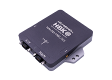
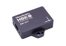
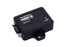
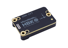
In 2016-18 LORD Sensing MicroStrain released its GX5/CX5/CV5 inertial sensor product line.
Each new generation brought significant improvement in inertial sensor performance, accuracy, and so forth.
Click here for a detailed technical note on migrating from the GX3 to the GX4.
Click here for a detailed technical note on migrating from the GX4 to the GX5/CX5/CV5.
The MEMS gyroscopes used on the LORD Sensing MicroStrain Inertial sensors are very high quality automotive/industrial grade gyros that have excellent temperature, linearity, and bias stability characteristics. They have very low noise and are stable over a wide range of dynamic conditions. However, like all MEMS gyros, there are conditions that can cause the zero-bias value to change.
Click here for a technical note that details this subject and instructs the user on how to use the “capture gyro bias” function to maintain the accuracy of the inertial sensor.
Adaptive filtering was introduced with the fourth-generation GX4 LORD Sensing MicroStrain devices, however, the adaptive thresholds on the GX4 are fixed and determined by the user. This legacy option is still available on the new fifth generation GX5/CX5/CV5 devices, but with its greater processing capabilities, these fifth-generation devices can offer the auto-adaptive option. There is no tuning required, which makes the new auto-adaptive filtering option more flexible, reliable, and easy to use.
Click here for a detailed technical note which discusses Auto-Adaptive Dynamic Roll & Pitch Performance.
From time to time, LORD Sensing MicroStrain releases firmware updates for its inertial sensors.
An Inertial Device Firmware Update Tool is always available on-line and by using it, a user can always update to the latest available firmware.
Click here for a technical note that describes the update process.
Follow the instructions below for the application you are using (SensorConnect or MIP Monitor) to generate a settings file. Once the file is created it can be set aside and imported to the inertial sensor at another time.
The settings file is also valuable in aiding LORD Sensing Microstrain in supporting you when troubleshooting problems.
Note: Settings files are not compatible between SensorConnect and MIP Monitor.
If you are using SensorConnect:
Apply desired settings to the inertial sensor through the Configure screen. When those are in place, do the following.
- Click Save/Load Settings.
- Click Export in the Export Settings section and the Export Inertial Config File window appears.
- Choose a file name and location to save the exported settings file.
- Note the directory so you can retrieve the file later.
- Click Save, the window closes and a settings file with the given name is written to the selected location. The file is a JSON (extension .json) file.
- A green notification message displays in the upper right corner of the screen to indicate success - on this message are buttons to open the new file or navigate directly to the file location.
If you are using MIP Monitor:
Make all the settings that you are normally applying to the inertial sensor. When those are in place, do the following.
- Click Settings.
- Click Export Settings and the Choose or Enter Path of File window appears.
- Accept the default File Name.
- Note what directory is in place (so you can retrieve the file).
- Click OK, the window closes, and a "Settings" file with a name like 3DM-GX5-15 6254.62027 Settings 6-7-2018 1-34-16 PM.ini is written.
Yes, the inertial sensor programming interface is comprised of a compact set of setup and control commands and a very flexible user-configurable data output format. The commands and data are divided into two command sets and one data set corresponding to the internal architecture of the device. The two command sets consist of a set of “Base” commands (a set that is common across many types of devices) and a set of unified “3DM” (3D Motion) commands that are specific to the LORD Sensing MicroStrain inertial product line. The data set represents the one type of data that the 3DM-GX5-10 is capable of producing: “IMU” (Inertial Measurement Unit) data.
Base commands: Ping, Idle, Resume, Get ID Strings, etc.
3DM commands: Poll IMU Data, Estimation Filter Data, etc.
IMU data: Acceleration Vector, Gyro Vector, etc.
The protocol is packet based. All commands, replies, and data are sent and received as fields in a message packet. Commands are all confirmed with an ack/nack (with a few exceptions). The packets have a descriptor type field based on their contents, so it is easy to identify if a packet contains IMU data, commands, or replies.
Yes, the 3DM-GX5-35 programming interface is comprised of a compact set of setup and control commands and a very flexible user-configurable data output format. The commands and data are divided into three command sets and two data sets corresponding to the internal architecture of the device. The three command sets consist of a set of “Base” commands (a set that is common across many types of devices), a set of unified “3DM” (3D Motion) commands that are specific to the LORD Sensing inertial product line, and a set of “System” commands that are specific to sensor systems comprised of more than one internal sensor block. The data sets represent the two types of data that the 3DM-GX5-35 is capable of producing: "GNSS" (Global Navigation Satellite System) data and “IMU” (Inertial Measurement Unit) data.
Base commands: Ping, Idle, Resume, Get ID Strings, etc.
3DM commands: Poll IMU Data, Estimation Filter Data, etc.
System commands: Switch Communications Mode, etc.
IMU data: Acceleration Vector, Gyro Vector, etc.
GNSS data: GNSS Position, Velocity, Satellite Data, Fix Data, etc.
The protocol is packet based. All commands, replies, and data are sent and received as fields in a message packet. Commands are all confirmed with an ack/nack (with a few exceptions). The packets have a descriptor type field based on their contents, so it is easy to identify if a packet contains IMU data, GNSS data, commands, or replies.
Yes, the inertial sensor programming interface is comprised of a compact set of setup and control commands and a very flexible user-configurable data output format. The commands and data are divided into four command sets and two data sets corresponding to the internal architecture of the device. The four command sets consist of a set of “Base” commands (a set that is common across many types of devices), a set of unified “3DM” (3D Motion) commands that are specific to the LORD Sensing inertial product line, a set of “Estimation Filter” commands that are specific to LORD Sensing navigation and advanced AHRS devices, and a set of “System” commands that are specific to sensor systems comprised of more than one internal sensor block. The data sets represent the two types of data that the inertial sensor is capable of producing: “Estimation Filter” (Attitude) data and “IMU” (Inertial Measurement Unit) data. The type of estimation filter used in the 3DM-GX5-25 is an Auto-Adaptive Extended Kalman Filter (EKF).
Base commands: Ping, Idle, Resume, Get ID Strings, etc.
3DM commands: Poll IMU Data, Estimation Filter Data, etc.
Estimation Filter: commands Reset Filter, Sensor to Vehicle Frame Transformation, etc.
System commands: Switch Communications Mode, etc.
IMU data: Acceleration Vector, Gyro Vector, etc.
Estimation Filter data: Attitude, Acceleration Estimates, etc.
The protocol is packet based. All commands, replies, and data are sent and received as fields in a message packet. Commands are all confirmed with an ack/nack (with a few exceptions). The packets have a descriptor type field based on their contents, so it is easy to identify if a packet contains IMU data, Estimation Filter data, commands, or replies.
Yes, the inertial sensor programming interface is comprised of a compact set of setup and control commands and a very flexible user-configurable data output format. The commands and data are divided into 4 command sets and 3 data sets corresponding to the internal architecture of the device. The four command sets consist of a set of “Base” commands (a set that is common across many types of devices), a set of unified “3DM” (3D Motion) commands that are specific to the LORD Sensing MicroStrain inertial product line, a set of “Estimation Filter” commands that are specific to LORD Sensing MicroStrain navigation and advanced AHRS devices, and a set of “System” commands that are specific to sensor systems comprised of more than one internal sensor block. The three data sets represent the three types of data that the inertial sensor is capable of producing: “IMU” (Inertial Measurement Unit) data, “GPS” (Global Positioning Sensor) data, and “Estimation Filter” (Position, Velocity, and Attitude) data. The type of estimation filter used in the inertial sensor is an Extended Kalman Filter (EKF).
Base commands: Ping, Idle, Resume, Get ID Strings, etc.
3DM commands: Poll IMU Data, Poll GPS Data, etc.
Estimation Filter commands: Reset Filter, Sensor to Vehicle Frame Transformation, etc.
System commands: Switch Communications Mode, etc.
IMU data: Acceleration Vector, Gyro Vector, etc.
GPS data: Latitude, Longitude, UTC, Satellites in view, etc.
Estimation Filter data: Position, Velocity, Attitude, Acceleration Estimates, etc.
The protocol is packet based. All commands, replies, and data are sent and received as fields in a message packet. Commands are all confirmed with an ack/nack (with a few exceptions). The packets have a descriptor type field based on their contents, so it is easy to identify if a packet contains commands, replies, IMU data, GPS data, or Estimation Filter data.
Yes, the inertial sensor programming interface is comprised of a compact set of setup and control commands and a very flexible user-configurable data output format. The commands and data are divided into four command sets and three data sets corresponding to the internal architecture of the device. The four command sets consist of a set of “Base” commands (a set that is common across many types of devices), a set of unified “3DM” (3D Motion) commands that are specific to the LORD Sensing inertial product line, a set of “Estimation Filter” commands that are specific to LORD Sensing navigation and advanced AHRS devices, and a set of “System” commands that are specific to sensor systems comprised of more than one internal sensor block. The data sets represent the three types of data that the inertial sensor is capable of producing: “Estimation Filter” (Position, Velocity, and Attitude) data, "GNSS" (Global Navigation Satellite System) data, and “IMU” (Inertial Measurement Unit) data. The type of estimation filter used in the internal sensor is an Auto-Adaptive Extended Kalman Filter (EKF).
Base commands: Ping, Idle, Resume, Get ID Strings, etc.
3DM commands: Poll IMU Data, Estimation Filter Data, etc.
Estimation Filter commands: Reset Filter, Sensor to Vehicle Frame Transformation, etc.
System commands: Switch Communications Mode, etc.
IMU data: Acceleration Vector, Gyro Vector, etc.
GNSS data: GNSS Position, Velocity, Satellite Data, Fix Data, etc.
Estimation Filter data: Position, Velocity, Attitude, Acceleration Estimates, etc.
The protocol is packet based. All commands, replies, and data are sent and received as fields in a message packet. Commands are all confirmed with an ack/nack (with a few exceptions). The packets have a descriptor type field based on their contents, so it is easy to identify if a packet contains IMU data, GNSS data, Estimation Filter data, commands, or replies.
